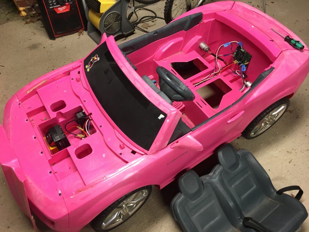
Walking through my neighborhood one day, I happened upon a pink Camaro Power Wheels style kids riding toy that someone was throwing away. It appeared to have been left outside for an extended period of time and was full of ants! I guessed that the car stopped working, probably due to being full of ants, and they decided to toss it rather than try to clean it up.
I have a young daughter at home that I knew would just love a pink convertible Camaro, so I grabbed it and decided to get it working for her.
The first thing I did was to rip out all of the wiring and switches. The entire setup was extremely simple. The car was powered by two small DC motors, one for each rear wheel. The motors look to be standard 550 size and were geared down quite a bit with plastic gearboxes. The shifting mechanism was two integrated switches that allowed for full speed forward, half speed forward, and reverse. The biggest surprise was that the foot pedal was simply a switch and did not allow for any sort of variable speed control! All of this was connected to a standard 12V lead acid battery.
All of the switch contacts were covered in dead ants and did not work, however, the motors worked perfectly. So, all I had to really do was replace the inexpensive switches and the car would be as good as new. But, how much fun is that (especially for someone that makes motors spin for a living)? This car really needed variable speed control and a lighter and more powerful battery system.
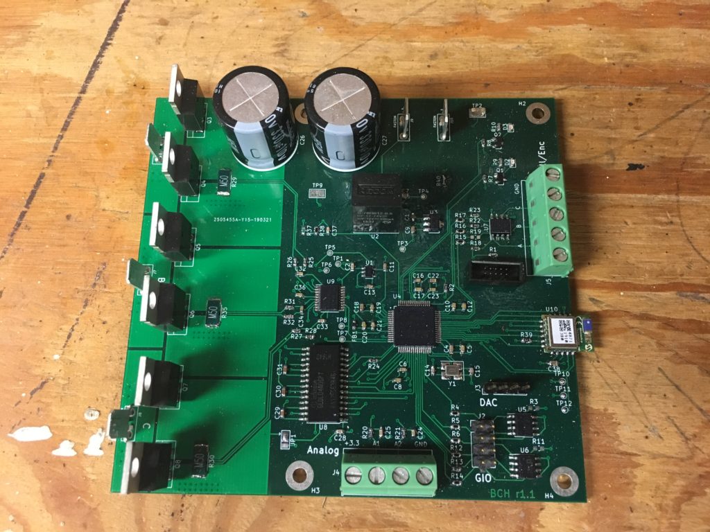
I happened to have already designed some hardware that would work perfect to add some functionality to this car (complete with a bluetooth radio for remote control).
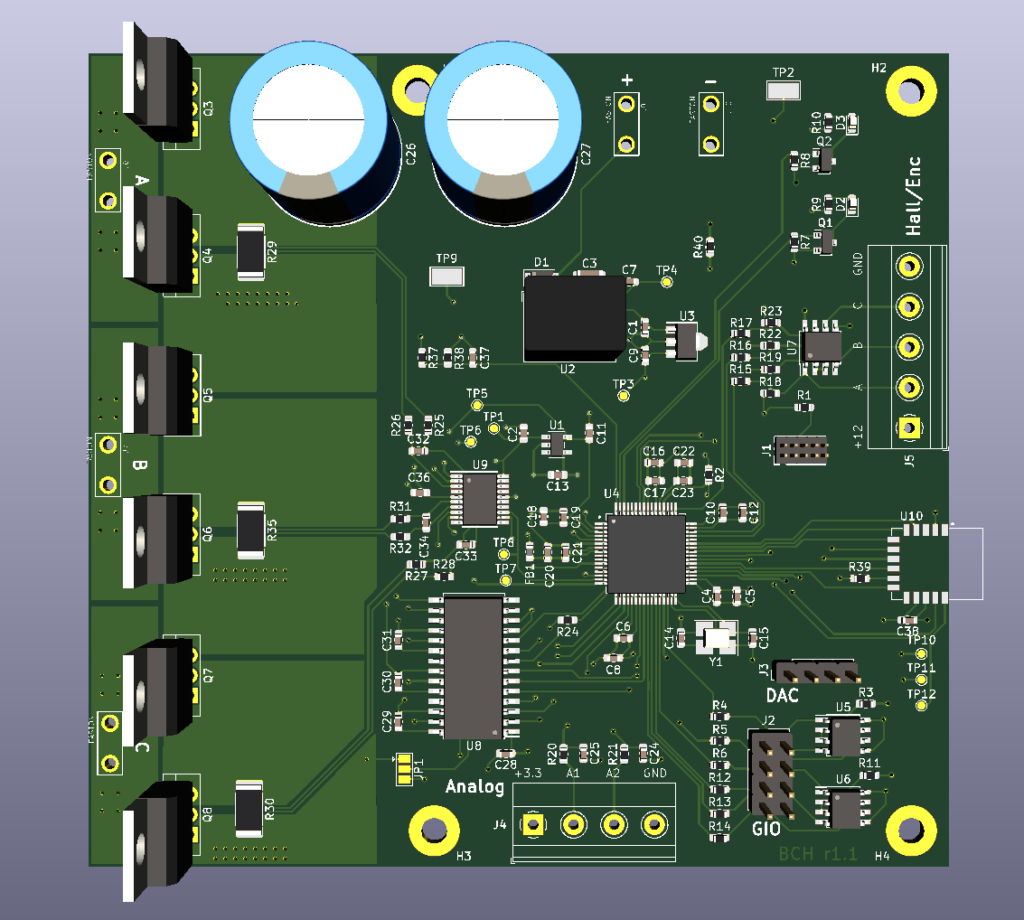
It was intended to spin 3 phase motors, so I could set it up as a chopper drive for the DC motors, wired in parallel, and use the bottom leg of the unused third phase for a braking resistor, if I thought it was necessary.
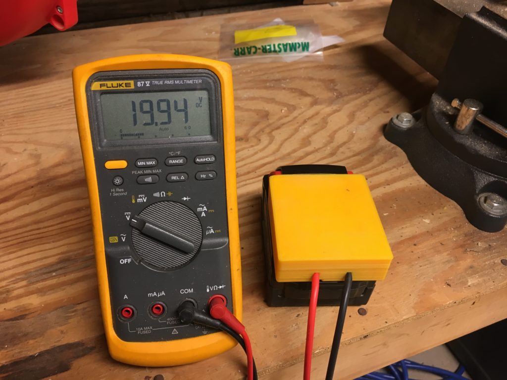
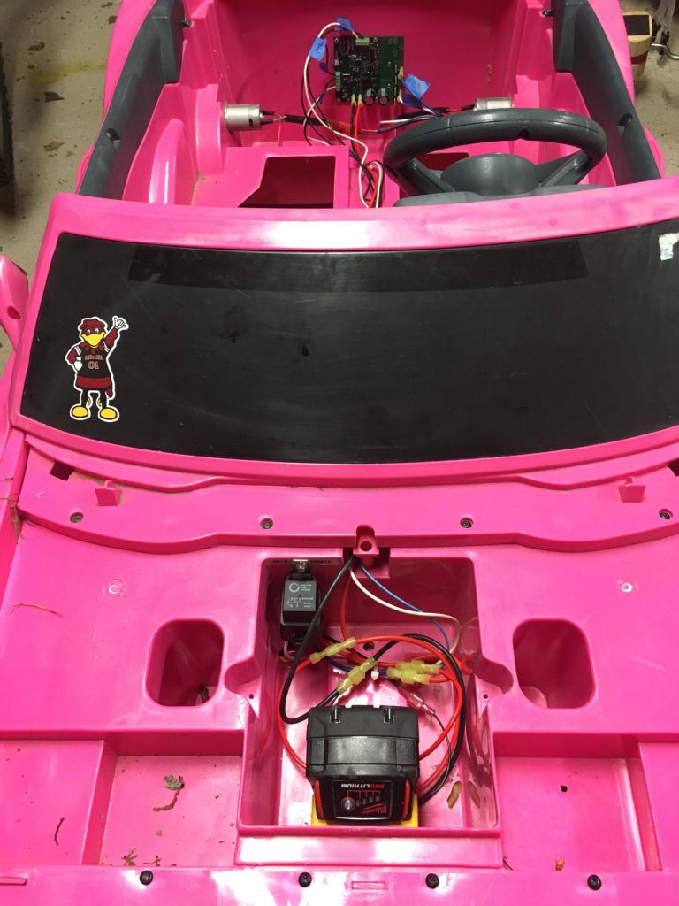
For battery power, I decided to use Milwaukee 18V lithium ion power tool batteries. I already had a few of these and the chargers for various cordless tools. It just so happens that some generous person has done the hard work of creating a model of the battery adapter all ready to be 3D printed. Not only does this outperform the 12V lead acid battery, it charges faster, and is much lighter.
The original car setup was limited to 30A using a circuit breaker. I decided to throw a 30A automotive fuse in line with the battery to ensure the motors are not over-driven. The battery and wiring fit perfectly in the spot that held the lead acid battery.
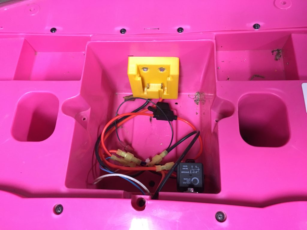
My daughter loves keys, so I added a keyswitch to the dashboard from a scooter that closes an automotive style relay and sends the battery power to the control board.

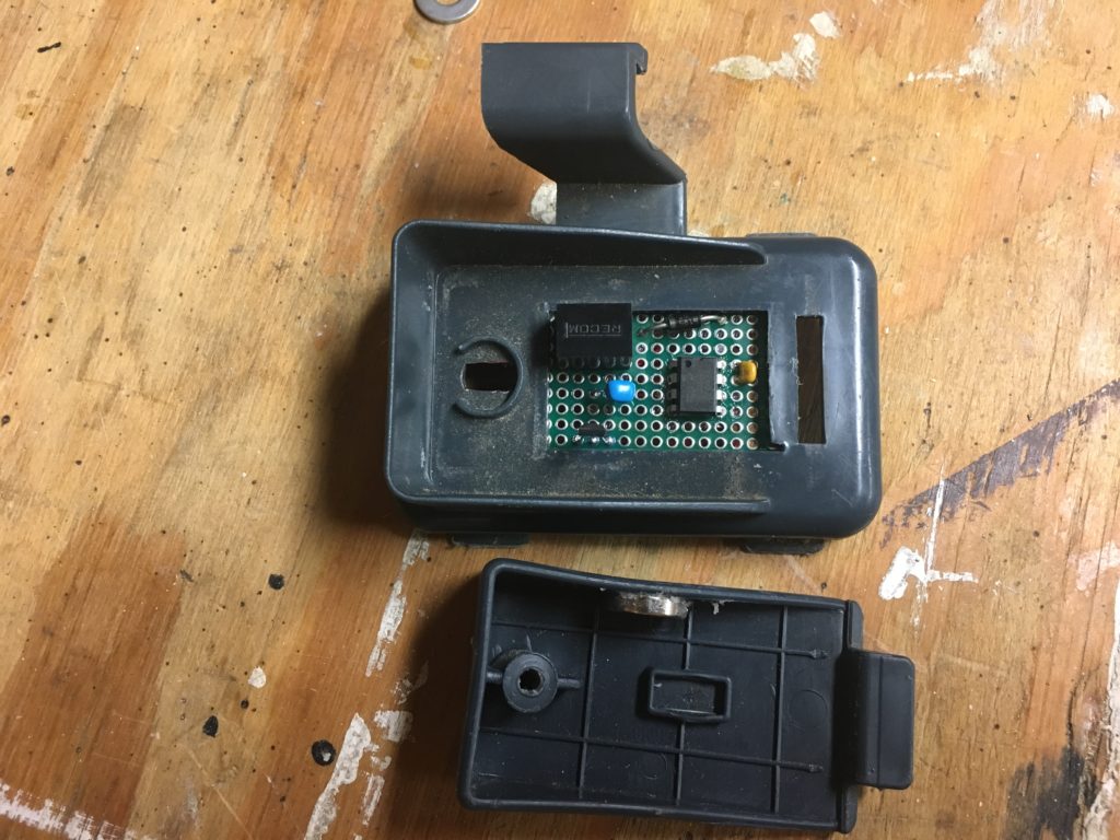
The foot pedal required a bit of engineering. I really wanted it to be variable speed. I also wanted it to handle being left outside in the elements and those pesky ants if they decide to return! The obvious choice was to add an analog hall effect sensor and magnet. The sensor output runs through a unity gain op amp and into the analog input of the control board.
At some point I intend to fab a proper board for the pedal, but my prototype is working great for now (with liberal application of conformal coating).
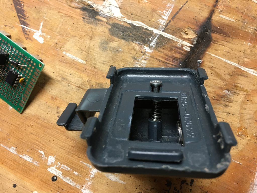
All the pedal needed mechanically was a spring with the correct tension. Testing shows that 7-10 lbs feels right.
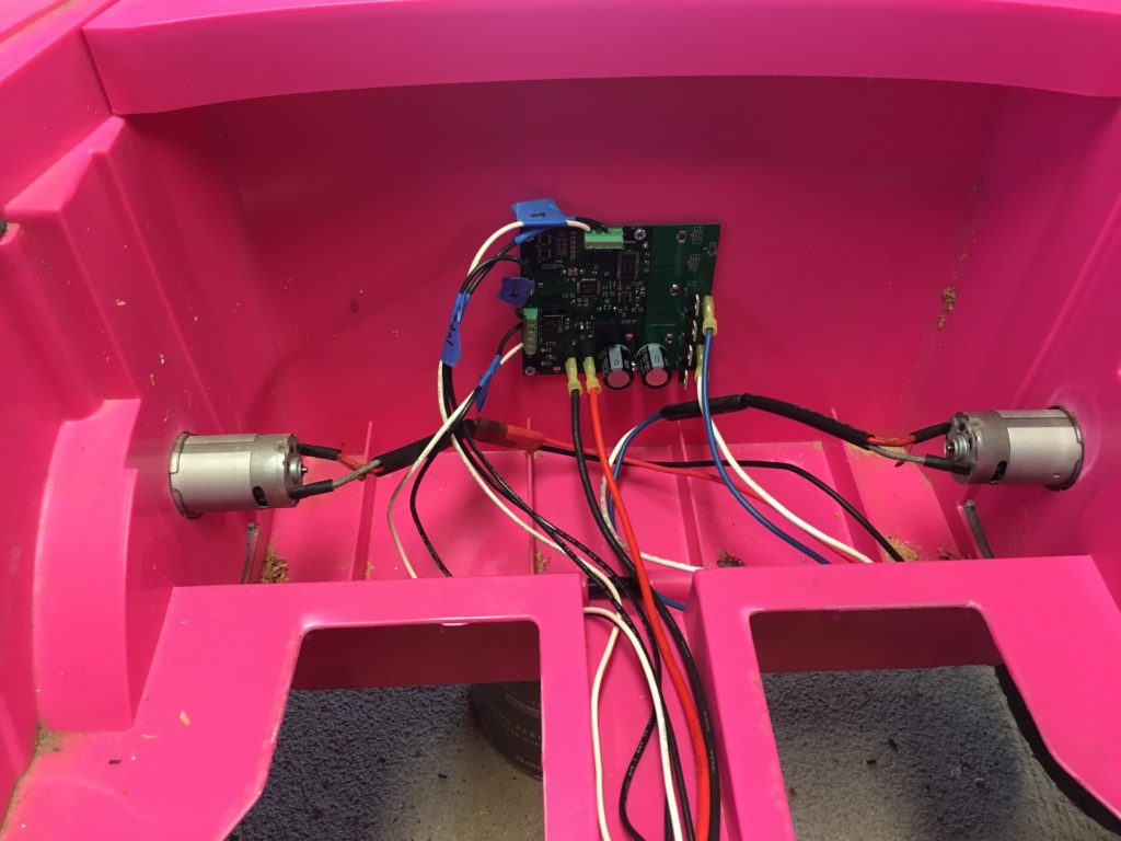
For the shifter, I simply replaced the switch with a working copy and did not use the middle half-speed position. I can configure the max speed and torque of the car over Bluetooth LE using my phone. The switch is connected to the Hall Effect/Encoder input on the control board since the car has no direct speed feedback.
The motors are connected in parallel to the A and B phases of the control board. I do not have the C phase connected to a braking resistor at this time because the drag from the gearboxes is enough to slow the car to my liking. The control is configured to allow the driver to shift the car into reverse when moving forward to brake and regenerate into the battery. However, I am not sure this is a good habit to teach my daughter!
Well, how does it work?
The M18 battery and chopper drive have increased the max speed of the car from 5 MPH to 9 MPH. It has a very smooth takeoff and can crawl at low speeds when using the variable speed pedal. The battery and control board are hardly stressed with the maximum current and torque settings I am using. I am planning on replacing the 30A fuse with a 40A fuse and increasing the max current as a test. The Bluetooth LE control lets me take over the pedal from my daughter as a safety measure and allows me to tune and configure the various drive parameters using my phone (I need to write a better app for this).
The simple answer is that I need more batteries because this car is in constant use!