Almost every company that develops microcontrollers (MCU) has a part or series of parts that is designed for motor and real time control. When used correctly, the parts I have worked with all perform admirably. Although I generally choose an MCU based on the price, peripherals, package type, and familiarity, there are performance differences between them beyond just the added features. This post is my attempt to measure the performance of a selection of MCU cores when executing a standard Field Oriented Control (FOC) loop. These tests are very application specific and mainly stress each MCU’s math, flash, and caching speed.
The Contenders
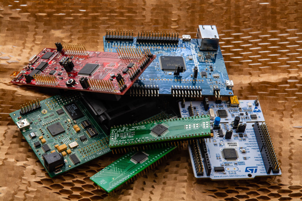
I chose a selection of MCUs that I have experience using, have the tools to develop, and cover a range of core types. The price varies greatly between the most expensive and least expensive MCU I tested. The exact part chosen depended more on availability of development boards than any particular application requirement. However, the overall family of each MCU has a variety of parts that cover a large range of price points and feature-sets. That said, following are the MCUs:
- dsPIC33CK256MP506 – This is easily the lowest cost MCU in the test and is also the only MCU that is 16-bit and does not have a floating point unit (FPU). This was chosen because it is a fairly new offering with a higher supported clock speed and offers a very interesting dual core option (dsPIC33CH series). The system clock runs at 180MHz max (see the note below about how Microchip describes the instruction clock and the issue I had with it running at 200MHz).
- TMS320F28069 – This is the MCU I used to initially develop my BLDC skateboard. I use Texas Instruments C2000 series MCUs extensively professionally and am familiar with the higher end Delfino series. This is the first time I have used the lower cost Piccolo series. The TI C2000 MCUs are highly optimized for real time control and I expect them to perform very well. This version contains a CLA, which is basically a separate floating point core that can execute code in parallel to the main processor. I will not be testing the performance with the CLA, although it is said to be slightly higher than the main core. The system clock runs at 90MHz max.
- ATSAME70Q21 – This is a blazingly fast ARM Cortex-M7 and represents the highest performance ARM MCU core available right now. Atmel developed this MCU and was later purchased by Microchip. My particular development board is still branded Atmel. The system clock runs at 300MHz max.
- PIC32MK1024MCF064 – This is Microchip’s MIPS32 microAptiv MCU optimized for real time control. Microchip chose MIPS over ARM for their initial 32-bit line, until they acquired Atmel and picked up their extensive selection of ARM MCUs. I am curious how it performs in comparison to the Cortex cores, clock for clock, and if Microchip was on to something by going the MIPS route instead of the very popular ARM. The system clock runs at 120MHz max.
- TMS320F28335 – This is the first Texas Instruments C2000 series MCU that offered an FPU and is in the high end Delfino category. I developed a selection of drive products that use this MCU. Newer Delfino series MCUs offer a CLA (described above) and a TMU, which is a trigonometric accelerator (this would greatly increase the park, ipark, and sensorless speed estimation performance of an FOC). This model does not offer either of these options, so it will be interesting to see how it performs clock-for-clock with the lower end Piccolo MCU. The system clock runs at 150MHz max.
- STM32F446RE – This is a popular high end ARM Cortex-M4 offering from ST. It seems like everyone that uses MCUs has an inexpensive STM32 development board laying around. I want to see how it compares clock-for-clock to the Cortex-M7. The system clock runs at 180MHz max.
FOC Test Loop
Each MCU runs the following control loop in an interrupt routine. The loop begins after the motor current measurement and ends after the space vector generator. I measure the time the loop takes to execute by toggling a GPIO pin and viewing the time between pulses on an oscilloscope. If the development environment offers a way to time loops internally, I use it to confirm my measurements.
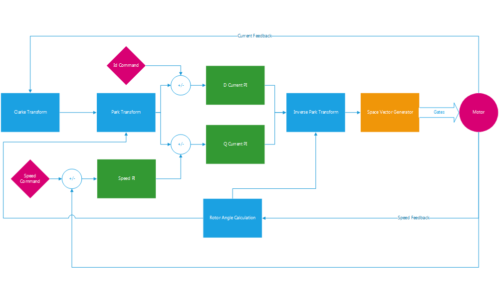
The FOC code is floating point for the MCUs that have an FPU unit and fixed point for the dsPIC. For fixed point, I use the XC16 compiler built-in functions to access the two dsPIC 40-bit accumulators and associated instructions for most of the math. The cos, sin, and sqrt functions are used from the XC16 fixed point library (libq.h). The output is normalized Q15 numbers. Here is an example fixed point park transform using the XC16 built in functions for the dsPIC:
volatile register int16_t aReg asm("A");

void ctrlParkCalc (ctrlPark *park)
{
aReg = __builtin_mpy(*park->alpha, *park->cosTheta, 0, 0, 0, 0, 0, 0);
aReg = __builtin_mac(aReg, *park->beta, *park->sinTheta, 0, 0, 0, 0, 0, 0, 0, 0);
park->D = __builtin_sacr(aReg, 0);

aReg = __builtin_mpy(*park->beta, *park->cosTheta, 0, 0, 0, 0, 0, 0);
aReg = __builtin_msc(aReg, *park->alpha, *park->sinTheta, 0, 0, 0, 0, 0, 0, 0, 0);
park->Q = __builtin_sacr(aReg, 0);
}
The floating point code uses the compiler standard math libraries for sin, cos, and sqrt. The output is normalized 32-bit float.
Results
There are a lot of variables to cover in this sort of testing. The results are separated into sections describing the various settings used to configure the MCUs and firmware variations.
Maximum Measured Performance
This compares the highest performance I was able to obtain with each MCU. Each is running at the maximum supported clock rate, with the best compiler optimizations, and best linker settings. Execution time is measured in microseconds.
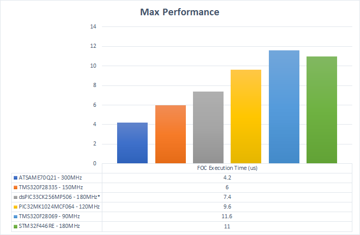
It is no surprise that, in general, the MCUs with the fastest clocks have the lowest FOC execution times. The TMS320F28335 seems to more efficiently execute the loop per clock cycle compared to the other parts. The STM32F446RE seems to be less efficient than the other parts.
*NOTE: The DSPIC33CK is stated to run at 200MHz, but my version is not stable unless I run it at 180MHz. I need to verify this with Microchip support. Also, Microchip separates the instruction clock from the system clock. The actual system clock runs at the listed frequency. The instruction clock is described to run at half that with each instruction requiring a single cycle. The reality is that each instruction takes two cycles: one fetch and one execute. I use the system clock value in all my comparisons.
Normalized to the Highest Clock Rate Supported
To really find out how efficiently the MCUs use each clock cycle, I ran the test loop at the highest common clock frequency that every part supports. This is 90MHz. Once again, all the MCUs are running with the best compiler optimizations and best linker settings.
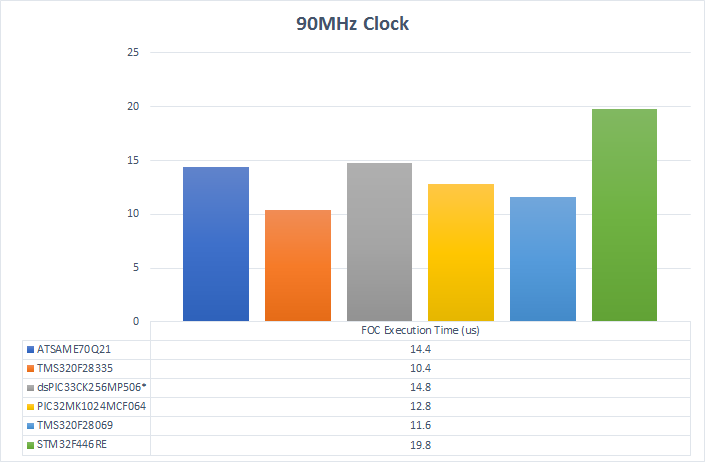
The C2000 MCUs show how well their instruction set is designed for this kind of control. This tells me that the newer Delfino C2000 MCUs with 300MHz clock rates would be very quick (not even considering the TMU). The spunky dsPIC, surprisingly, stays right with the Cortex-M7. The built-in DSP instructions are highly optimized.
Pre-Fetch Cache and Flash Speed
MCUs that run at high clock speeds can execute code faster than it can be retrieved from the onboard flash storage. When the MCU waits for the code to be retrieved, it wastes clock cycles and is inefficient. This is partially bypassed by pre-fetching the code and storing it in fast cache memory. The faster and more effective the flash access and pre-fetch routines are, the faster the MCU can execute code.
However, no caching routine is perfect, so MCUs will still need to wait periodically. The dsPIC has a very simple pre-fetch and cache mechanism. This means that every instruction takes exactly the same amount of time all the time (except for branches). This can be beneficial in some instances.
The other MCUs in this test have complicated pre-fetch and cache systems. To test how well this works, I modified the FOC routine to be copied into RAM on start up and executed from RAM each cycle. This bypasses the need to use the cache for most of the FOC code minus some of the standard library calls.
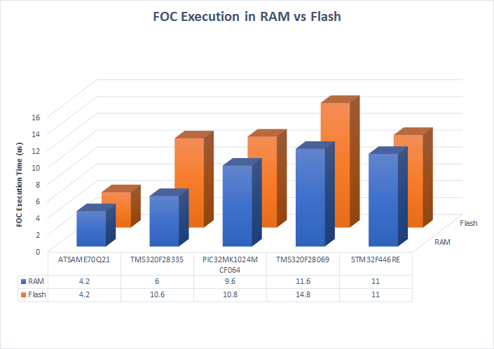
Both of the ARM Cortex parts have exceptionally fast flash access and caching. There was no discernible difference between executing the code from RAM than from flash. The C2000 series MCUs, however, greatly benefited from execution in RAM. All the comparison times for the C2000 chips, unless otherwise noted, execute the FOC control from RAM.
The PIC32MK is a bit of a mystery. The revision of the chip I am using has some cache errata where the predictive prefetch cache mechanism can cause errors. Thus, I have that portion of the caching system disabled. A newer revision his this fixed. My hope is that the newer revision of the MCU will perform the same from RAM as from flash. The cache is doing something. Disabling it completely tripled the execution time. All the comparison times for the PIC32MK chip, unless otherwise noted, execute the FOC control from RAM.
The need to run code from RAM has an impact on the system as a whole. It means that the MCU is only achieving its best peformance for the code that is run from RAM. Because the RAM on these processors is much smaller than the flash, it is not always possible to execute all of the code in RAM. This forces the developer to make decisions on what is most time sensitive and hope that it can fit in the available RAM when resources are scarce.
Fixed and Floating Point Execution Speed
The other MCUs have DSP extensions similar to the dsPIC. This test shows how using those extensions with fixed point math compares to floating point math. I re-wrote the FOC loop using the Texas Instruments IQmath library. These are highly optimized fixed point routines designed for the C2000 series of MCUs. Similarly, this shows the performance impact that running a floating point FOC loop on an MCU without an FPU has compared to using fixed point math. Both MCUs in this comparison are running at their max clock rate.
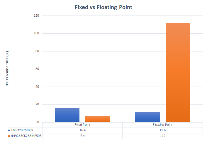
The IQmath fixed point routines turn out to be markedly slower than using the FPU. But, they are fairly close to the fixed point dsPIC numbers running at the equivalent clock speed.
Not surprisingly, using the software floating point routines on the fixed point dsPIC is an order of magnitude slower. If an algorithm benefits from floating point math, it really makes sense to use an MCU with an FPU.
Compiler Optimization
In my experience, it is rare that using -O2 optimizations make anything slower or introduce new bugs. This is normally my default setting when compiling code for production. However, the Microchip XC series of compilers require a license fee to unlock optimizations above -O1. This shows how much faster the FOC loop executes with -O1 optimizations compared to -O2.
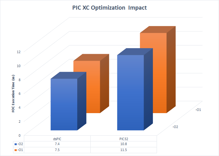
Is the -O2 optimization worth the extra cost in this instance? It is definitely not worth the price for the dsPIC using the already optimized code. The PIC32 depends on the situation. Every piece of software responds differently to these optimizations and Microchip does give you a time limited demo of the paid compiler to do your own tests. Nonetheless, all the comparisons are using -O2 optimizations for all the MCUs. -O3 optimizations did not have any notable performance increases on any of the MCUs.
32-Bit MCU Normalized Performance
Finally, this shows all the highest performance 32-bit floating point MCUs running at the maximum common clock rate of 120MHz.
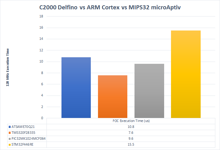
This is a clearer picture of the second chart and tells me that there might be something to Microchip choosing MIPS32 for their real time control optimized MCUs. Clock-for-clock the C2000 and MIPS32 are faster than the ARM Cortex parts in this application. This bodes well for the new C2000 Delfino series MCUs that operate at 300MHz and have the TMU and CLA.
Conclusions
While the FOC loop used in testing is comparatively simple to most used in real applications, it did provide a method to test the math and flash performance of various motor control microcontrollers in a fixed manner. The control loop will always need to be executed in a finite amount of time as field oriented control increasingly gets more complex. Choosing an MCU that can execute this code most efficiently is an important part of development.
Overall, I am impressed with the performance of all the MCUs tested. The C2000 series seems to be the most effective at real time control loops. I am sure the parts with the TMU, CLA, and dual cores even enhance the performance further. The dsPIC had a very strong showing for price sensitive applications where the control loop can be calculated in fixed point. Finally, the MIPS32 and ARM Cortex-M7 MCUs showed that they belong in the conversation with the other more specialized MCUs.
Which MCU is the best? That is for you to decide. For me, the peripherals make the big difference. The C2000 MCUs have very powerful PWM and ADC peripherals and not much errata.
Update 1
I decided to test out an Atmel/Microchip ATSAME54P20A Arm Cortex-M4 and compare it to the STM32F446RE tested above. The ATSAME5 MCU runs at 120MHz max as opposed to the STM32F4 at 180MHz max, so I expect the 180MHz part to be faster at that speed. However, how do they compare at 120MHz?
ATSAME5 – 120MHz : 12.4us
STM32F4 – 120MHz : 15.5us
They have the same core, so the performance difference must come down to flash access times, caching, and wait states.
Update 2
The issue with the dsPIC33CK256MP506 that prevented it from properly running at 200 MHz are that the reserved bits FDEVOPT<9:8> must be zero as specified in the datasheet. They are one in the default state. The easiest way to ensure that they are cleared is to specify all the configuration bit settings. Even setting the bits to their default state will force those reserved bits to zero. My test code only specified the minimum configuration bit settings and did not specify any bits in the FDEVOPT settings.
I am successfully and happily using the dsPIC33CK256MP506 in a project running at full speed without issues.
Update 3
The PIC32MK1024MCF064 is now not recommended for new designs. It has been replaced with the PIC32MK1024MCM064 that offers equivalent peripherals and a fully working cache.
It would be interesting to see how newer parts perform. For instance, TI now has F2837x, F2838x, and F28004x parts. Are there similar upgrades from other microcontroller companies?
Thanks for commenting! There are similar upgrades from other companies. However, the basic performance per clock cycle should be about the same. For example, the F2837x ups the clock a bit and simply adds another core and CLA. The F2838x series looks extremely nice with the integrated communication options, and I plan on grabbing an evaluation of them once they are out of preview. If I find the time, I will run another set of tests with the newer TI MCUs.
… which reminds me that I am due for another post regarding some recent fun projects I have done
It would be great if you compare the power consumption of these devices.
The objective is to do a specific job faster and colder.
If a 300MHz processor does it faster while consuming less power comparing to a 200MHz processor, is the frequency difference an issue or disadvantage?
Hello Brian,
I was curious if you could make your FOC reference C code available. I am interested in exploring what architectural knobs affect performance the most and improving the MCU architecture.
Thanks
Nagendra
Do you have a thought on arithmetic limitations of fixed point MCU’s wrt. to floating points? How do you run PI controllers with coefficients higher than 1? Does your test include extra implementations required for such over range calculations?
When using fixed point math, you determine the magnitude of the variables and the precision needed. Then, you scale them accordingly. For example, the proportional gain of a PI regulator might be scaled by 2^11 to create a Q11 value. This gives you a range of 15.996 to -16 in a signed 16-bit integer. If you multiply this by a Q15 error (error scaled by 2^15), the result is a number scaled by 2^26. Thus, you store the result of the multiplication in a 32-bit variable, then right shift it by 9 bits to obtain a Q15 number again. Some DSPs give you accumulator registers to do this math that is more efficient. The dsPIC series of MCUs give you two 40-bit accumulators that allow a margin above using a 32-bit integer as storage for a multiplication and will handle saturation.
The new STM32G4 series MCUs and certain STM32H7 series now feature a CORDIC co-processor for trigonometric acceleration with 20-bit precision in fixed point. They are significantly faster than the ARM math libraries for trigonometric functions. Additionally they have “CCMSRAM” connected through separate instruction and data buses, which allows execution from SRAM without bus stalls for accessing data. I wonder how much of an impact this would have. I have a custom FOC algorithm with sensorless observer requiring 7.5uS at 170MHz (which would translate to 10.6uS at 120MHz). It does a few more advanced things like position lookaheads and deciding on which position estimate to use.
Nice! That is similar to what TI offers in their C2000 series and makes a pretty substantial impact on the execution speed of the transforms. Unfortunately, those C2000 MCUs are hard to get right now. If that continues, I’ll need to look into those new ST MCUs.