In Part 1, I determined what components were needed to turn the motor I found. Now I need to figure out how to make the motor turn the skateboard wheels.
The most straight-forward way to spin the wheel is to simply attach the skateboard wheel directly to the motor shaft. However, I want to make sure I have enough torque available to get the board moving with me on it. Thus, I plan on using either a belt or chain with sprockets on the motor shaft and attached to the inside of the wheel. This will allow me to use gear reduction to gain some extra torque.
This brings up some more questions:
- How much gear reduction is possible before the top speed of the skateboard is too low?
- What top speed is possible to begin with and what is too fast?
Luckily, I have an old skateboard laying around to do some tests, a decent hill nearby, and a GPS to record my speed. I discovered really quickly that 20 MPH is more than fast enough for me right now!
To determine the theoretical top speed of the motor and skateboard combination, we need to look at the motor specification sheet. It says that the theoretical unloaded max speed of the motor is 5270 RPM. We might be able to hit that going downhill, but my weight, friction, and air resistance will greatly reduce the speed the motor can attain under normal circumstances.
Using the diameter of the skateboard wheels, we should be able to calculate the theoretical max speed of the skateboard with an unloaded motor. Then, we can adjust the gear ratio to make this max speed close to 20 MPH. It is not realistic to think this will actually hit 20 MPH, unless we run the motor at higher than rated voltage and current. I am fine with that for now as 20MPH is beyond the absolute max speed I feel comfortable going at this time and I am not sure how much torque is really needed to even move yet!
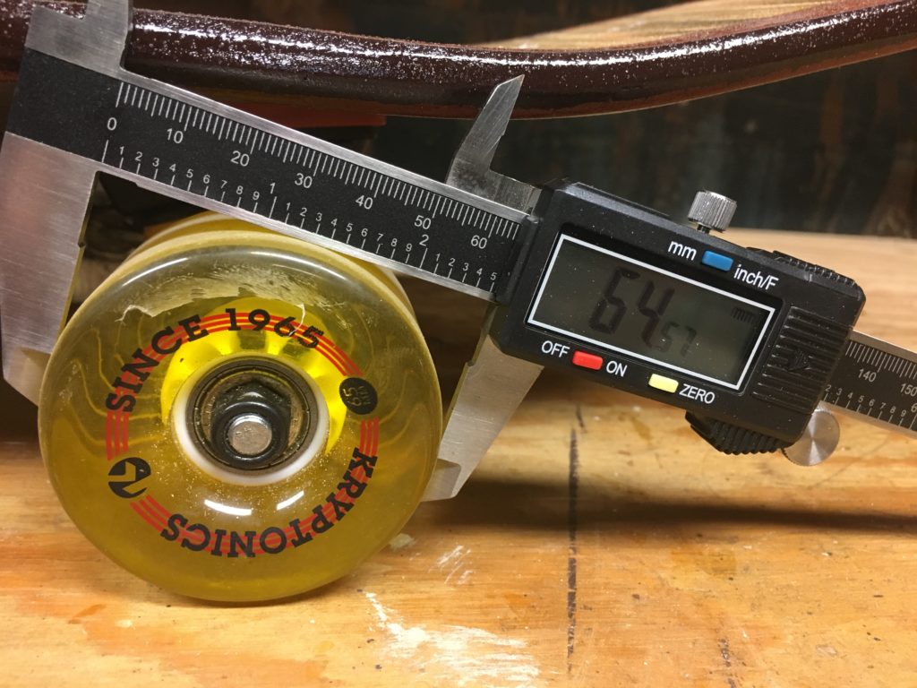
64.57mm * (0.03937in / 1 mm) * 3.14159 = 7.9863 inches per revolution of the wheel
(5270 rev / minute) * (7.9863 inches / rev) = 42087.801 inches / minute
(42087.801 inches / minute) * (1 mile / 63360 inches) * (60 minutes / 1 hour) = 39.85 miles per hour (!)
So, we can gear reduce the output of the motor 2:1 to reach our 20 MPH goal.
Now that we know the gear reduction we want, we need to find the sprockets, chains, and belts that will both fit our 1/4 inch motor shaft and fit inside the 2.5 inch circumference of the wheel while providing around a 2:1 gear reduction. Is that too much to ask?
Luckily, there is a place called McMaster-Carr. It has just about any kind of random piece of hardware imaginable. Like Timing Belts and Pulleys. They happen to have a 1.094 inch timing belt pulley that will fit the motor shaft and a matching 2.017 inch pulley that I can modify to fit the inside of the wheel. The important thing is that both pulleys use the same 3/8 inch timing belt and that width belt is available in 1 inch circumference increments from 5 inches to 77 inches.
That means I have tons of options for how and where the motor mounts, which we will determine in Part 3.